The Solution

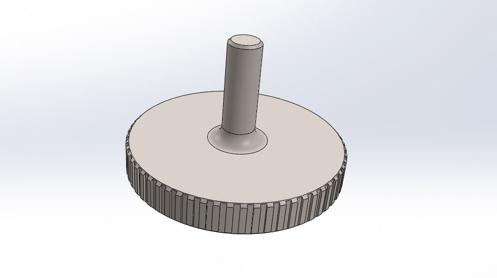
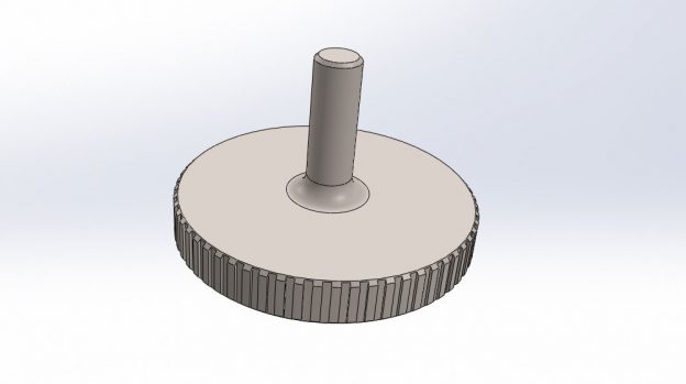
Our client had an idea of what they wanted the feet to look like; they provided us with an artistic rendering and a specification for the design. The 3D CAD model could then start to be produced by our design engineers, as this would be needed for the machining process; this process of 3D modelling was done in our CAD software SolidWorks. With SolidWorks able to render components to look like the real finished part, several screen shots were taken of the finished 3D CAD model with a polished stainless steel finish, allowing the client to see what the feet will look like. While the rendered images of the feet were being created and checked with the client, the material was located in the factory.
From SolidWorks to CNC Machining
With the client’s approval of the 3D CAD model, machining could start. The 3D data was then passed onto one of our many CNC engineers where the part was imported into PowerMill, our CAM software. Within PowerMill all the tool paths used to machine the component could be created, as well as choosing the correct tools for the operation. The objects were then machined on one of our many CNC machining centres. Once finished, the components were highly polished by one of our model makers to meet our client’s high standards.
To find out more about this case study or any of our other ones please call us on 01279 2036550.


